
Brandy’s Gain Formula
Gi = ZPn/Zi
Brandy’s Gain Formula applies to
passive circuits. It states that the circuit gain from an input to a
circuit node n, is the parallel combination (ZP) of the Impedances connected to
node n divided by the connecting impedance (Zi).
Brandy’s Gain Formula is the corner stone of K9 Analysis. Most of the K9 concepts come from Brandy. If you are familiar with Legacy circuit analysis, you may find the concepts strange. In K9 analysis, circuits propagate signals from inputs (voltages) to outputs (voltages). The circuit operation is described by the input to output gain. Instead of voltage and current, K9 uses gain.
In passive circuits signals can propogate thru Impedances in two directions. There is a source node, a destination node and a connecting Impedance. Every node has a node Impedance (ZPn) which is the parallel combination (ZP) of all the Impedances connected at the node. ZPn is the impedance from node n to ground if all the interfacing nodes are at ground potential. In circuit operation the apperent Impedance may be different due to feedback. You don't have to consider this. K9 will handle feedback for you. Just consider the node Impedance and the input impedance.
A formal description of Brandy's Gain Formula is presented on the Technical Brandy Page. On this page Brandy will describe the circuit implications.
One application of Brandy's Formula is a replacement for the Potential divider equation. Lets look at a Single Input circuit and compare the analysis procedures:
|
Single Input |
|
|
Potential Divider |
Brandy |
|
|
|
|
V2 = R2 / (R1 + R2) * V1 V2 = 2K / (1k + 2K) *1 V2 = 2/3 *1 = 0.667 |
V2 = ZP2/R1 * V1 ZP2 = R1 // R2 = 1k // 2k = 667 V2 = 667 / 1k *1 = 0.667 |
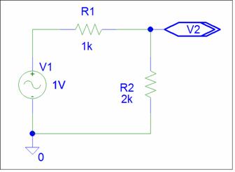
The potential divider solution is simpler if you just want the output voltage value. Brandy calculated the the output node Impedance, ZP2. This is the Source Impedance for the V2 output. This circuit is equivalent to a 0.667 Volt source with a 667 ohm source Impedance. Brandy calculated the gain from V1 to be 0.667.
If you want to make changes, you
can change R1 or R2 to get any gain less than one. If you need to
maintain the output source resistance, you need to change R1 and R2.
Let’s look at two inputs. Both solutions use Superposition.
|
Two Inputs |
|
|
Potential Divider |
Brandy |
|
|
|
|
V3 = V3 (top ) + V3 (bottom ) V3 (top) = (R2 // R3 / ( R2 // R3) + R1) * V1 V3 (top ) = ( 2k// 3k / (2k//3k) + 1k) * 1 V3 (top ) = (1200 / 1200 + 1K ) *1 = 0.545 V3 (bottom) = (R1 // R3 / ( R1 // R3) + R2) * V2 V3 (bottom ) = ( 1k// 3k / (1k//3k) + 2k) * 2 V3 (top ) = (750 / 750 + 2K ) *2 = 0.545 V3 = 0.545 + 0.545 = 1.09 |
V3 = ZP2 / R1 * V1 + ZP2 / R2 * V2 ZP3 = R1 // R2 // R3 = 1k // 2k // 3K = 545 V3 = 545 / 1k * 1 + 545 / 2k * 2 V3 = 0.545 + 0.545 = 1.09 |

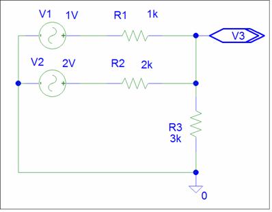
The Potential Divider procedure requires you to analyze two different circuits. In the top circuit, V2 is replaced by a short; in the bottom V1 is replaced by a short. Brandy’s procedure always uses one circuit and is simpler for two or more inputs.
K9 assumes Superposition .
You never have to replace other voltage sources with a ground. This
is done automatically.
The circuit has inputs
V1 and V2. V1 has a 1 volt magnitude and 1k source impedance. V2
has a 2 volt magnitude and a 2k source impedance. For the 3k load the output contributions are
equal. If
we short the output, both sources will have a current of 1ma. What about
other output impedances? Are they equal for all values of R3? Brandy says Yes.
Brandy’s Gain formula says that the gain is inversely proportional to the connecting impedance. The gain from V1 will have twice the magnitude of the gain from V2. This is totally hidden by the potential divider equation. If you have lots of circuit experience, you may have suspected this, but rejected the concept because of the potential divider equation.
If I want to change a gain, can I just change the connecting impedance value? Brandy says No, you need to change two impedances. The connecting impedance is included in the node impedance. Changing the node impedance will effect all gains.
With the potential Divider approach, you have two circuits to consider and some equations to solve. This makes circuit changes difficult. You can experiment with variable resistors (didle box) , simulation, or use K9.
Let's assume that we want to increase the V1 gain by 10% without changing the V2 gain. The equation approach is too difficult for Brandy. She also does not have the patience for the experimental approach. You're welcome to try these.
Let's look at the circuit from Brandy's point of view:
The circuit has two inputs, two gains, and a node impedance.
V3 = 0.545 * V1 + 0.272 * V2 ZP2 = 545
V3new = (0.545 * 1.10) V1 + 0.272 V2
Brandy says that if you keep the same node impedance, changes will not affect the other gains. Lets keep ZP2 = 545. To get the new gain for V1, we need to change R1.
R1 = ZP2 / gain = 545 / (0.545 * 1.10) = 909
R1 is included in ZP2. A change of R1 will change ZP2. To maintain the ZP2 node impedance value, you need to change the ground resistor R3.
1/ZP2 = 1/R1 + 1/R2 + 1/R3
1/R3 = 1/ZP2 - 1/R1 - 1/R2 = 1/545 - 1/909 - 1/2k = 1/4260
Increasing R3 to 4260 ohms will compensate for the R1 reduction. We now the a new circuit.
Too dificult ? Let Shadow do it for you. Just remember to give him the node impedance plus the gains. He will design the circuit. If the node impedance is not changed, the other input resistor values will not change.
The key to circuit changes is the node impedance. If you maintain the node impedance, changes will not affect other inputs. Each change will require two resistor changes, the input resistor and the ground resistor. In some cases this will result in a negative resistor value. This means that you tried to violate Daisy's Theorem.
The sum of the gains must be equal to one. For passive circuits, each signal gain will be less than one and the ground gain adds the gain needed to comply with Daisy. You can think of the ground gain as spare gain. Circuit changes shift the gains. Decreasing a signal gain is never a problem, the ground gain increases. Increasing signal gain is a problem if the increase is greater than the ground gain. The ground resistor will become negative; difficult to implement.
Brandy has lots of circuit intuition and is
more than willing to share her knowledge. In a circuit the local gain is
inversely proportional to the connecting impedance and directly proportional to
the node impedance. This gain equation applies to all connections in a
linear circuit. Multiple connections pose no problem. Just add the individual
contributions.
If you have struggled with passive circuits,
this will require some contemplation. If you accept Brandy’s
Formula, Passive circuits can be Dog-Gone Simple.
Brandy is no longer with us. I ask that
you honor her by keeping her name with this passive gain formula.
Whenever you see a connecting impedance or a ZP term,
think of Brandy and remember that the gain is inversely proportional to the
connecting impedance.
.