
Shadow's Design Procedure
In Electronics when you design a circuit, you select the circuit and use the design procedure for that circuit. There are different procedures for inverting amplifiers, non-inverting amplifiers, differential amplifiers, etc.
Shadow combined the
different Legacy Design procedures into a single procedure. Instead of
selecting a circuit, you only need to specify the desired gains. The procedure
will design a passive or single op-amp active circuit.
Sound too good to be true?
Design Procedure
1. The first step in the design procedure is to determine the desired gains.
Vout = g1 * V1 + g2 * V2 …. + gn
*Vn
The inputs, V1 to Vn, are ideal voltage inputs, they have zero source
impedance. You can have any number of inputs. The gain can be positive,
negative, or complex.
2. The second step is to use Daisy's Theorem to determine the ground gain.
G0 = 1 - (g1 + g2 + ... +gn)
If all the gains are positive, you can use the passive design procedure. Although the Passive procedure is mathematically correct for all cases, it generates negative impedance values for negative gains. The active procedure generates positive impedance values for all cases.
Passive
Design Procedure
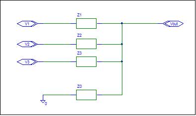
3. Select a Parallel Impedance Value. This will be the Output Source Impedance Value. Try ZPout = 1k.
4. Calculate Input Impedance Values using Brandy's Gain Formula.
Zi = ZPout / gi
Each input has an input Impedance whose value is equal to ZPout divided by the gain. If g0 = 0, then no ground input Impedance is required. Otherwise, treat ground as an input with gain g0.
5. Check the design.
Calculate the value of Zpout. It should be equal to the value chosen in step 3.
A comparison between the legacy procedure and the K9 procedure is shown on the passive examples page.
Active Design Procedure
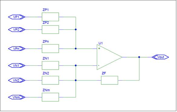
3. Select a Feedback Impedance Value. Any value can work. Try Zf = 100k.
Connect Zf between the op-amp output and the "-" op-amp terminal.
4. Calculate Input Impedance Values using Plato's Gain Formula. Assume ZP+/ZP- = 1.
Zi = ZF / |gi|
Each input has an input Impedance whose value
is equal to ZF divided by the magnitude of the gain.
If g0 = zero, then no ground input Impedance is required. Otherwise, treat ground as an input with gain g0.
Positive gain input Impedances ( ZPi ) connect from the positive input ( VPi ) to the "+" op-amp terminal.
Negative gain input Impedances ( ZNi ) connect from the negative input ( VNi ) to the "-" op-amp terminal.
5. Check the design.
Calculate ZP+ and ZP-. They should be equal.
The active procedure can design most op-amp circuits, inverting amplifier, non-inverting amplifier, summing amplifier, etc. A bonus is that the op-amp is designed for minimum bias current error.
A comparison between the legacy procedure and Shadow’s procedure is shown on the active examples page.
Shadow always creates a balanced design which
is preferred by Op-amps. The design may contain Impedances which are only
required for balance. You can identify these Impedances via Ozzie s Rule.
Shadow will design a circuit for any linear
circuit equation using no more than one op-amp.
You can have any number of inputs.
There is no restriction on the gain values. A non-inverting gain with a
gain value less than one is allowed. For
fun, try some special cases such as Vout = Vin, or
Vout = 0.
This is too easy.
What’s the catch? There are a few requirements. Ideal operation is assumed for
the op-amp. The input must be an ideal voltage source. The gains must be
specified. Complex values are allowed.
If you are familiar
with the Legacy design procedures, this may appear absurd. Positive gains are totally
different than negative gains. Assuming that all gains are Rf/Ri
is wishful thinking. The fact that the positive gain is indeed Rf/Ri for balanced circuits has been discovered by others
independently. With lots of algebra you can shown that the positive gain is Rf/Ri, if ZP+ is equal to ZP-.
What about the
ground gain? Why does step 2 calculate a ground gain? Ground is zero volts, and
no matter what the gain is, ground can not contribute to the output. This is
true. Shadow calculated the ground gain to force the sum of the gains to be
equal to one. He knows that circuits are good citizens and obey all circuit
laws. Daisy’s Theorem is a circuit law. Adding the
ground gain allows the procedure to create a legal circuit. If the gains don’t
add to one, the circuit can’t work as intended.
What’s necessary in
the procedure? The ground gain is necessary to create a legal circuit. The
common gain formula is sufficient, but not necessary. Shadow used Plato’s Gain formula and assumed that p is equal to one.
You can use any value for p as long as the same value is applied to all
positive gains. You also need to modify the check to verify the selected p
value.
Plato’s Gain
formula suggests an alternate design procedure. Assume p =1. Pick an Rf value (100k). Use Rf/|gain|
to calculate Ri values.
Add an impedance to ground to balance the
design. You can use Daisy’s
Theorem as the check. This procedure can be simpler for complex gains.
The Legacy solution,
for multiple gains, is to use two op-amps. The Two Op-amp page compares Shadow’s design with the Legacy
two op-amp design.
No matter which
procedure you use, K9 makes op-amp design Dog Gone Simple.
Shadow is my walking companion. He’s kept me healthy. I ask that you honor him by keeping his name
with the design procedure.
If you wonder why the K9 Design Procedure has not been included in Legacy texts, complain to your text author. I have tried without success.